Introduction
In this tutorial, we’re going to write C# editor scripts and shaders to capture stereoscopic panoramas from within the Unity editor that we’ll be able to use as skyboxes, environment maps, and more.
The technique we’ll be exploring is adapted from a paper published by Google called Rendering Omni-Directional Stereo Content. The paper describes a technique for rendering stereoscopic panoramas within a rasterization-based renderer, and provides pseudocode implementing the technique.
We’ll be adapting that pseudocode into C# and HLSL shaders, and optimizing it for use inside the Unity editor. Unlike many of the assets available on the Unity Asset Store to capture stereoscopic panoramas in-engine, we will not be using compute shaders, meaning this technique should work on any platform the Unity editor runs on.
That said, this is an offline technique; we won’t be capturing these images during live gameplay. On my box, it takes about 20 seconds to render a pair of 4,096-pixel-wide panoramas using this technique.
Understanding the problem
Actually capturing a static panoramic image with correct stereoscopy when viewed from any angle turns out to be a very hard problem. The traditional methods we have for capturing these images end up breaking down when we try to use them to render stereo images.
Monoscopic cubemaps
The standard method for capturing omni-directional images for use in 3D graphics, whether as skyboxes, environment maps, or for other effects, is the cubemap.
A cubemap is a collection of six square images, each captured with a 90-degree field of view in each direction (up, down, left, right, front, back).
The Unity manual provides a quick rundown of cubemaps. Wikipedia has more in-depth coverage of the topic.
We can imagine wrapping the six images around the faces of a cube, like assembling a cardboard box.
Cubemaps are easy to capture with a standard camera in any rendering environment, and capturing six separate images minimizes the amount of distortion.
We could capture more images with a narrower field of view to even further reduce distortion, but the images would not be square in shape, which introduces additional complexities.
When we project the same six images onto a sphere instead, the cubic distortion disappears and it no longer looks like six separate, perspective images. It’s a powerful illusion.
Furthermore, cubemaps are supported in hardware by many GPUs, making them potentially quite efficient.
As you can see, monoscopic cubemaps are a very well-understood, mature technology that is even supported in hardware. Surely it should be easy to tweak this technique to make it stereoscopic.
Issues with capturing stereoscopic cubemaps
The standard approach to stereoscopic rendering is to render the scene twice, once for each eye, from two cameras placed side by side.
The distance between the cameras is called the interpupillary distance (i.e., the distance between the pupils), and it should be about 6.4 centimeters.
So our first stab could be rendering two separate monoscopic cubemaps, one for each eye, from cameras placed about 6.4 centimeters apart.
Independent monoscopic cubemaps
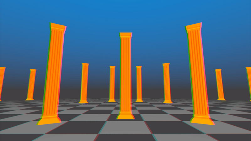
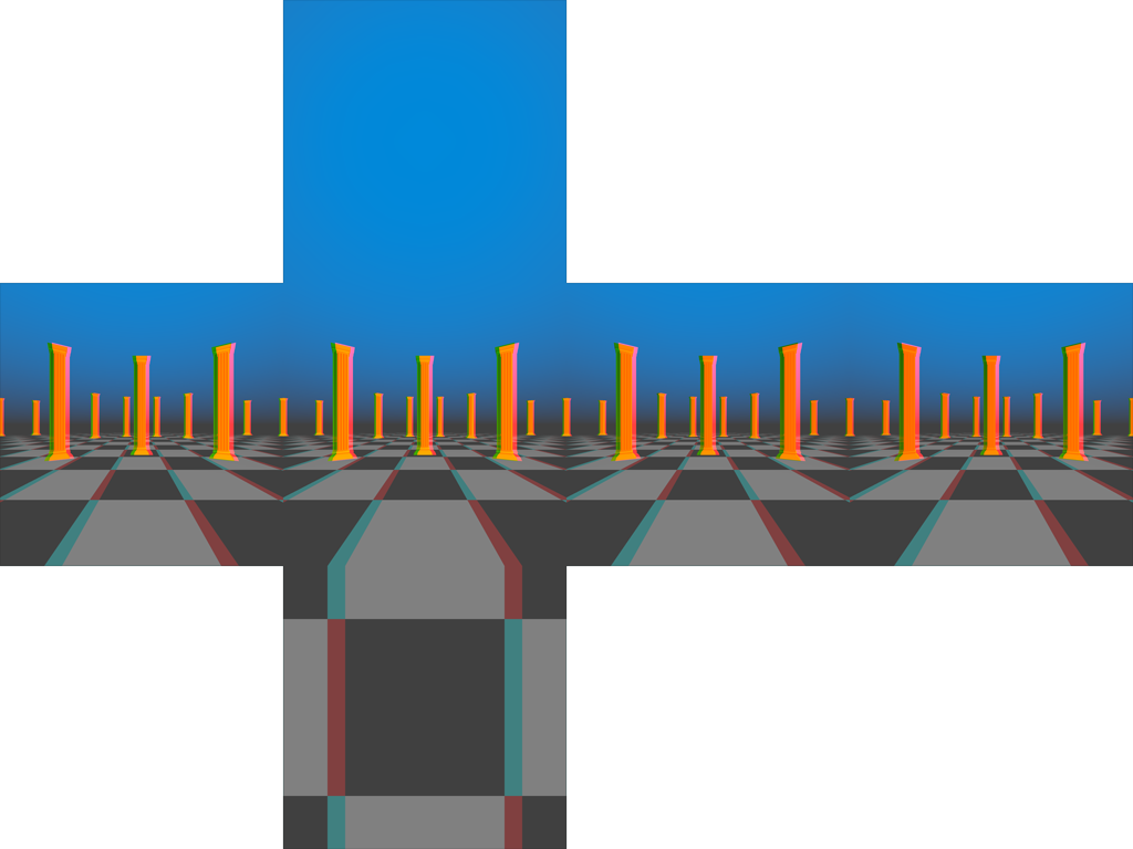
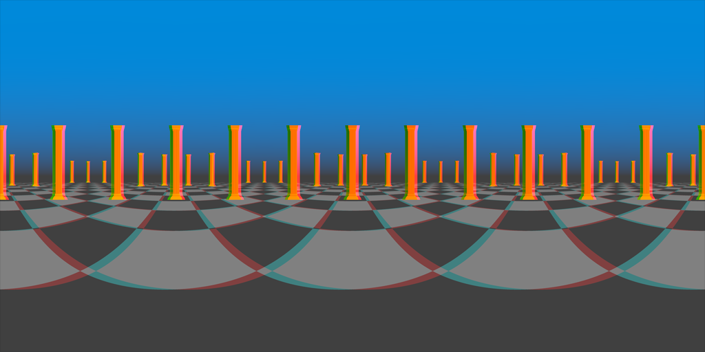
Above is a cubemap I’ve rendered in just that way. I’ve composited two separate cubemaps together as an anaglyph to help us analyze the images and determine if they meet our requirements. I’ve also exaggerated the interpupillary distance to 20 centimeters to make it easier to see exactly how the cubemap for each eye differs from the other.
Unfortunately, we have some problems here.
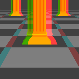
If we look at the front face of our cubemaps (the square in the center of the cross), we’ll see more-or-less correct stereoscopy. The left and right images get more and more similar as objects become farther from the viewer, while nearer objects in the left eye image are positioned to the right of their counterparts in the right eye image.
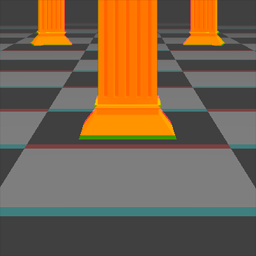
The right face of our cubemaps look very different. We would expect to see similar stereo separation regardless of which direction we look, but on the right face, we have no horizontal separation.
Instead, we have vertical separation: objects in the left eye image appear farther away than their counterparts in the right eye image. The effect is reversed on the left face.
This is because we are rotating the cameras in place. It’s effectively what you would see if you turned each of your eyes 90 degrees to the right, not what you would see if you turned your head 90 degrees to the right.
That’s some extreme side-eye!
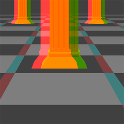
Finally, we have the back face of the cubemap. At first glance, this is correct and the only problem we have will be with the left and right faces. Unfortunately, on closer inspection, we can see that the left and right images are swapped.
Essentially, when each camera is turned 180 degrees to the rear, the "right" camera is to the left of the “left” camera.
The problems here all stem from the fact that the cameras representing our eyes are each rotating independently. When we turn our heads, our eyes are both rotating around a central point (somewhere around the bridge of our nose).
That is, our eyes are simultaneously rotating in space, and moving through space. So let’s try that with our cameras.
Rotating around a central point
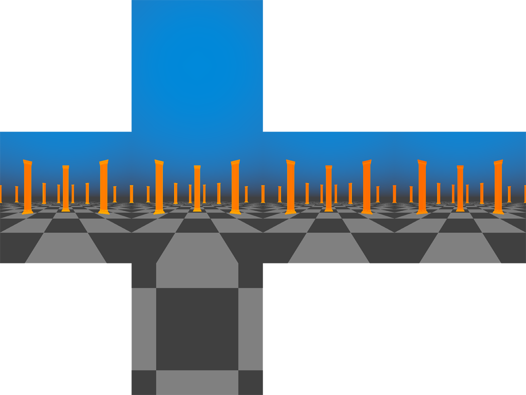
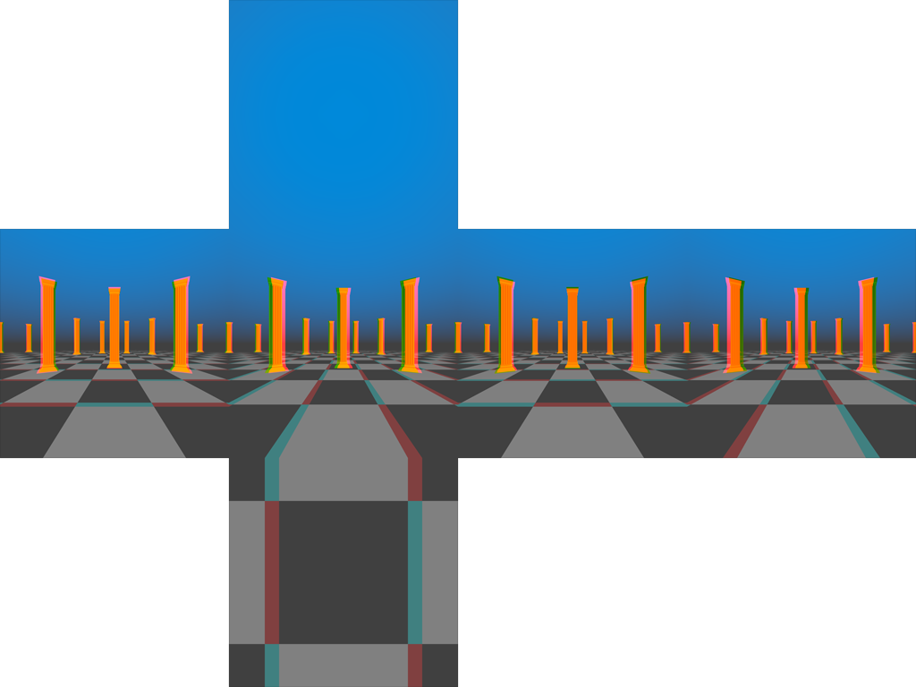
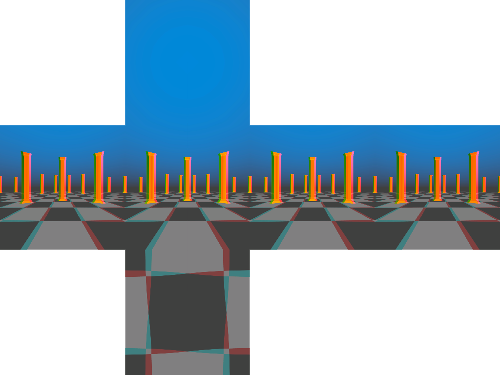
Above is an anaglyph of two cubemaps I generated by rotating the cameras around a central point in between rendering each individual face.
No off-the-shelf cubemap capture implementation will do this for us, so I had to write my own script.
Looking at the lateral faces (front, back, left, and right), each face is exhibiting comparable stereo separation. None of the issues we identified with the previous cubemap are present here.
Instead, we have some new problems.
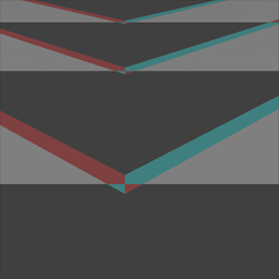
We have very visible seams between each image. Rotating a single camera in place with a 90-degree field of view adds up to exactly 360 degrees across the four lateral images. Once we begin moving the cameras, we have a visible offset between each image.
You may argue that these seams would be far less noticeable with a tighter interpupillary distance, and can be easily touched up in Photoshop, and you’d probably be right.
Unfortunately that’s not the biggest of our problems.
The bottom faces of both the cubemaps we’ve generated so far are identical and they are both wrong.
This image will exhibit correct stereoscopy if we face forward, and then look down.
But if we face right and then look down, we’ll be viewing this image rotated 90 degrees counter-clockwise. It will be as though our right eye is positioned above our left eye.
We’ll see similar problems when facing other directions.
Capturing two independent cubemaps for each eye is just not working. If you’re like me, you’re beginning to wonder if it is even possible to solve this problem.
Understanding the solution
I said above that capturing static panoramas with correct stereoscopy when viewed from any angle is a hard problem, but I lied. It turns out that it is impossible.
In order to achieve correct stereoscopy, we would need to capture a separate image for each eye for each possible viewing angle. At that point, we’re better off rendering the scene interactively.
However, it is possible to achieve an acceptable approximation that looks correct from many angles, and convincing from most others. The technique described in the Google paper will allow us to do just that.
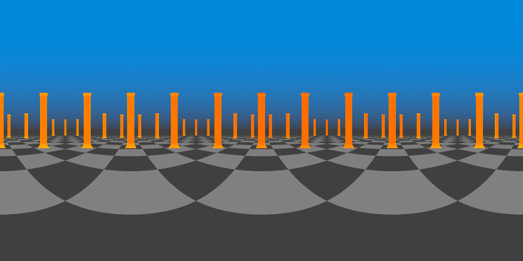
Equirectangular panoramas
Equirectangular panoramas are an alternate format for omni-directional images with very different properties from cubemaps.
Equirectangular panoramas are not frequently used in interactive graphics for a variety of reasons. Compared to cubemaps, they can introduce more distortion, especially at the poles (the top and bottom of the image).
Equirectangular panoramas are captured with spherical cameras, which are trivial to implement in a raytracer, but not in a rasterization-based renderer. If we are to stitch one of these together out of multiple perspective renderings as we did with the cubemap, we’ll lose some image fidelity to the squashing and stretching we’ll need to apply to convert a perspective projection to a spherical one.
Finally, they aren’t supported in hardware, which means we’ll incur the expense of evaluating trigonometric functions per-pixel if we want to do lookups into them as-is.
Typically, if we want to use an equirectangular image in an interactive scene, we’ll convert it into a cubemap first, and we’ll sacrifice some image fidelity in the process.
For monoscopic content, equirectangular panoramas don’t have a lot of benefits to us. However, they’ll make capturing convincing stereoscopy possible (though still not easy!).
Later, we’ll be able to re-import them into Unity and convert them to cubemaps.
Adding stereoscopy
The fact is, it is not physically possible to create a single panorama that accurately captures stereo separation of each eye. We would need an image for each eye for each possible viewing angle.
However, we can approximate it. That’s the central thesis of the Google paper. Google’s strategy is to bend the rays of incoming light around the circle representing the distance between the eyes. In a raytracer, altering the incoming camera rays is a trivial procedure; in a rasterization renderer like the graphics pipeline, we can’t manipulate the camera rays directly.
Google’s method is to rotate the camera around the circle, capturing a single column of pixels at each position, and stitching these one-pixel columns into a single equirectangular image. In order to get a complete 180-degree vertical field of view, we’ll capture two images with a 90 degree field of view at each orientation, one angled 45 degrees up, the other angled 45 degrees down. We’ll also be using a shader to correct our perspective camera to an equirectangular projection.
The code
To begin with, let’s create a new folder to organize all our scripts. I’ve called mine StereoPanoCapture.
Inside that folder, we’ll create another folder called Editor. Since we’ll only be capturing panoramas inside the editor, we can exclude these scripts from our build. (We’ll also be bringing in the UnityEditor namespace to create a UI for capturing panoramas, and we need to keep all that inside an editor folder.)
The StereoPanoCapture class
Inside the Editor folder, create a new C# script. I’ve called mine StereoPanoCapture.cs which matches the name of the class inside. This class will just be responsible for rendering the panorama images via static methods. Later, we’ll create a separate class that inherits from EditorWindow to house our UI.
Remove all the contents of the default class Unity creates, and remove the inheritance from MonoBehaviour. This is a plain C# class and we won’t be attaching it to any game objects.
using UnityEngine;
using UnityEditor;

public class StereoPanoCapture
{

}
Let’s dive into Google’s pseudocode. They provide us with three functions. The first, GetRayForODSCamera, is listed under their raytraicing example, but we’ll be using it to orient the camera each time we render. The second, RenderODSImage, is our main entrypoint, and it outputs a single equirectangular image for one eye. The third, ProjectToODS, reprojects a one-pixel column captured with a 90-degree field-of-view to one half (top or bottom) of an equirectangular image. We’ll be implementing this as a shader that operates over the entires stitched equirectangular image using Graphics.Blit.
Since these functions are provided as pseudocode to fully describe the algorithm, there is a lot of room for modifications to improve compatibility with Unity and several performance optimizations to be discovered.
Inside the class we’ll need two methods that map more or less to the GetRayForODSCamera and RenderODSImage functions of Google’s pseudocode. We’ll call them GetRays and Render for simplicity. GetRays is only called from the Render method, so it can and should be private. Both methods should be static, and we can leave the return types void and the argument lists empty for now.
static void GetRays()
{

}

public static void Render()
{

}
The GetRays method
Let’s look at GetRayForODSCamera first, because how we handle this function will have a big impact on the rest of our code. This function is called by RenderODSImage twice per pixel column to get the position and rotation (as a forward vector) of the camera. The function is called once to tile the camera up by 45 degrees, and again to tilt it down. It assumes the midpoint between the eyes is at the origin, which is fine for us. We’ll assign the position to the camera transform’s local position, and attach it to a parent game object if we want to capture a panorama from another position.
Inside GetRayForODSCamera, we’re calculating the values of two variables, theta and phi, which represent angles in radians, and . These angles measure our rotation around the panorama (as we rotate both eyes in a circle about the origin), and our rotation above or below the horizon, respectively.
One thing to note about this formula is that the value of (and thus of and ) is entirely dependent on the value of x, but we call the function twice in RenderODSImage inside a loop passing in the same value for x each time (once to tilt the camera up, and another time to tilt it down). If we can reconfigure this function to return all the data we need or both camera orientations in one call, we can avoid calculating theta and those expensive trigonometric functions twice.
But there’s an even bigger optimization to be found here. The angle (and thus and ) is entirely dependent on the argument y, but we only ever call this function with two values of y: and . We can precalculate and for those two values and assign them to constants.
As it turns out, and are and respectively (that’s 45 degrees in radians). The sine and cosine of are bothe the same: , and this is also the value of . The value of is . So we really only need to store one constant value, which we’ll call sinPhi, and we’ll negate it when the time is right. Since we calculate these values in a loop for each pixel of image width, this is going to save us a lot of cycles.
The value of , rounded to single-precision floating point, is 0.7071068f.
Add this constant to your class, outside of the methods:
const float sinPhi = 0.7071068f;
Furthermore, the camera forward vectors output by this function are going to be identical for a given column of pixels whether we are rendering the right eye or the left. The only difference is the camera position will be flipped across the origin. This means we can futher optimize this algorithm by rendering both eyes together and only performing these calculations once for both eyes. We’ll do this at the expense of increased memory use (we’ll be storing texture for both eyes in memory simultaneously instead of one at a time).
So, this means our GetRays function needs to return a position and two forward vectors. Instead of trying to return all that as a single object, let’s use our arguments and leave the return type as void.
The argument x in GetRayForODSCamera is essentially a texture coordinate, so I’m going to rename it u for clarity (it doesn’t really have anything to do with the axis of our scene).
We can also drop the eye argument, because we’ll be calling this function just once for both eyes and then flipping the position across the origin (which is as simple as scaling the position vector by ).
static void GetRays(
        float u,
        out Vector3 position,
        out Vector3 upDirection,
        out Vector3 downDirection)
{

}
Great! Now let’s calculate theta, just as in the Google pseudocode:
float theta = u * 2f * Mathf.PI - Mathf.PI;
Let’s also calculate out the sine and cosine of theta, since we’ll be using those values more than once in constructing our output:
float sinTheta = Mathf.Sin(theta);
float cosTheta = Mathf.Cos(theta);
Finally, we can use cosTheta, sinTheta, and our sinPhi constant to assemble our three output vectors:
position = new Vector3(cosTheta, 0f, sinTheta);
upDirection = new Vector3(sinTheta * sinPhi, sinPhi, -cosTheta * sinPhi);
downDirection = new Vector3(upDirection.x, -sinPhi, upDirection.z);
Now we’re ready to use these rays to render our images.
The Render method
Let’s begin thinking about the inputs and outputs of our Render method. We’re going to produce both eye images at the same time, so we need to return 2 Texture2D objects. The simplest way to do this is probably as an array.
We’re going to need to know which camera we’re rendering from, the desired distance between the eyes (called the interpupillary distance), and the desired width of our output images. (Equirectangular images are always twice as wide as they are high.)
public static Texture2D[] Render(
        Camera camera,
        float interpupillaryDistance,
        int imageWidth)
{

}
The rendering algorithm can be split into three parts: setting up, looping over each pixel of width to render vertical slices, and then stitching and reprojecting the slices together. Google does their stitching and reprojection inside the loop itself, but we’ll get better performance from Unity’s graphics APIs by moving some of that work to the end.
Let’s add some structure to our function by adding that central loop:
for (int slice = 0; slice < imageWidth; slice++)
{

}
The first few lines of Google’s pseudocode for RenderODSImage are calculating out some variables, so we’ll do that, too. Since we’ll be doing a lot of looping in this method, it’s worth it to precalculate these values up front even though the calculations are simple. Add the calculations above the for loop.
First, we can calculate the output images’ height based on the width:
int imageHeight = imageWidth / 2;
Next, we’re going to need to know how high in pixels each of the one-pixel wide slices we’re rendering is. Since we’re using a 90-degree field of view and tilting the camera up and down, this is half the total image height:
int sliceHeight = imageHeight / 2;
Finally, we’re going to need the radius of the circle our two virtual eyes are rotating around. That will be half the interpupillary distance:
float radius = interpupillaryDistance * 0.5f;
Since we’re going to be moving our camera around inside our loop, let’s also record the current position and rotation of our camera so we can restore them after we’re finished rendering. We’ll do this above the loop, after the variable declarations above:
Transform cameraTransform = camera.transform;
Vector3 originalPosition = cameraTransform.localPosition;
Quaternion originalRotation = cameraTransform.localRotation;
Let’s also set the field of view to 90 degrees, and save the original field of view for later:
float originalFieldOfView = camera.fieldOfView;
camera.fieldOfView = 90f;
Finally, let’s keep track of the camera’s current target texture (just in case there is one), and sub in a render texture that’s the appropriate size for each of our slices:
RenderTexture sliceTexture = new RenderTexture(...);
RenderTexture originalTargetTexture = camera.targetTexture;
camera.targetTexture = sliceTexture;
originalTargetTexture will be null if none was already assigned to the camera, but that’s alright because all we’ll be doing with it is assigning it back at the end. We also need to make the slice render texture our active render texture so we can copy pixels out of it inside our loop:
RenderTexture originalActive = RenderTexture.active;
RenderTexture.active = sliceTexture;
Skip over the loop for now. At the end of our method, we can reassign all these values and release the texture we’ve rendered our slices to:
cameraTransform.localPosition = originalPosition;
cameraTransform.localRotation = originalRotation;

camera.fieldOfView = originalFieldOfView;
camera.renderTexture = originalRenderTexture;
RenderTexture.active = originalActive;
sliceTexture.Release();
There’s another thing we need to do before we start looping, and that’s create textures to assemble our slices into. We’ll create one texture for each eye:
Texture2D leftEyeTexture = new Texture2D(
        imageWidth,
        imageHeight,
        TextureFormat.RGB24,
        false);
Texture2D rightEyeTexture = new Texture2D(
        imageWidth,
        imageHeight,
        TextureFormat.RGB24,
        false);
And we’ll return these textures in the last line of our method:
return new Texture2D[] {leftEyeTexture, rightEyeTexture};
The render loop
Finally it’s time to dive into our render loop, which is the heart of our implementation. Our loop executes once for each pixel of image width. Inside this loop we need to position our camera for both the left and right eyes, orient it up and down by 45 degrees, and render one slice of our panorama in each of these four positions (left up, left down, right up, and right down). We also need to copy each of those slices into the correct location in one of our output textures.
Let’s begin by positioning and orienting the camera. First we need to calculate the position for each eye and the up and down forward vectors, and we’ll do that with one call (per loop iteration) to GetRays. The u argument is a float between 0f and 1f representing the horizontal position of our slice in our output images. Adding 0.5f to our slice index both converts it to a float (so we don’t end up doing integer division unintentionally), and centers it on the pixel:
float u = (slice + 0.5f) / imageWidth;

Vector3 position;
Vector3 upDirection;
Vector3 downDirection;

GetRays(u, out position, out upDirection, out downDirection);
Now we can calculate a rotation based on the forward vectors returned by GetRays:
Quaternion upRotation = Quaternion.LookRotation(upDirection);
Quaternion downRotation = Quaternion.LookRotation(downDirection);
The position output by GetRays is always going to be one unit from the origin. We need to scale it to our interpupillary radius, then we’ll pose our camera in each of our four rendering positions and orientations:
position *= radius;

cameraTransform.localPosition = -position; // negative x == left, positive x == right
cameraTransform.localRotation = upRotation;

// render upper left slice
camera.Render();

cameraTransform.localRotation = downRotation;

// render lower left slice
camera.Render();

cameraTransform.localPosition = position;
cameraTransform.localRotation = upRotation;

// render upper right slice
camera.Render();

cameraTransform.localRotation = downRotation;

// render lower right slice
camera.Render();
The only problem with this code, is that each call to the camera’s Render method is overwriting the contents of our slice render texture. We need to copy the contents of that texture into our output textures in between calls.
We can copy into the output textures using the destination texture’s ReadPixels method. This method takes a Rect defining the area of the active render texture (which will be our camera’s target texture) to copy pixels from, and two integers defining the bottom left coordinate (where is the lower left pixel) of the destination texture to copy into.
For the upper left slice, this copy operation looks like this:
leftEyeTexture.ReadPixels(
        new Rect(0, 0, 1, sliceHeight),
        slice,
        sliceHeight);
I’ll leave the other three copy operations to you. Each copy operation should occur immediately after the corresponding call to the camera’s Render method. Remember that the destination coordinates represent the bottom left pixel of the rectangle to be copied into, and our pixel indices begin at in the lower left corner of the image. This means our lower slices will have a y index of 0.
The Rect defining the area of the slice render texture to copy from will remain the same, so we could make this code easier to read by putting the Rect in a variable and moving it above the loop.
After the loop, we need to call the Apply method on each of our eye textures. This will internally finalize all the changes we made with ReadPixels so the data can be read back or saved. Because Apply can be an expensive operation, we always want to call it after as many modifications as possible.
leftEyeTexture.Apply();
rightEyeTexture.Apply();
That completes our render loop. The last thing we need to do is reproject our images from a perspective projection to an equirectangular projection. We’ll do that after the render loop, after we reset the camera, before we return our left- and right-eye textures.
Equirectangular reprojection
Google provides us with the algorithm for reprojecting from a 90-degree field of view perspective projection to a properly spherical equirectangular projection in the ProjectToODS function. However if we translate their pseudocode as is, we’ll be performing that reprojection on each slice individually on the CPU. It will be much easier (and more performant) to move this work to the GPU and perform it using a single call to Graphics.Blit for each eye, but we’ll have to make some changes to Google’s algorithm to make that work.
To begin with, in order to use Graphics.Blit, we need to be blitting from a texture to a separate render texture. So we need to create a new render texture we’ll use just for this operation:
RenderTexture reprojectionTexture = new RenderTexture(imageWidth, imageHeight, 0);
RenderTexture.active = reprojectionTexture;
sliceTexture.Release();
Since we’re reassigning the active render texture here, we can slip these lines in just before we release our slice render texture, in place of reassigning the original active render texture.
Next we want to call Graphics.Blit to copy our left-eye texture to the render texture using a custom shader. To do this, we need a material encapsulating our shader, so add a material to our Render method’s arguments:
public static Texture2D[] Render(
	Camera camera,
	float interpupillaryDistance,
	int imageWidth,
	Material reprojectionMaterial)
{
Material objects need to be explicitly destroyed when we’re done with them, so it’s easier for us to let the method’s caller worry about that. Later if we want to produce many panoramas in a loop, we can construct just one material and dispose of it at the end.
Now we can blit from each of our eye textures using the reprojection material and copy the render texture contents back. Here’s how that looks for the left eye:
Graphics.Blit(leftEyeTexture, reprojectionTexture, reprojectionMaterial);
leftEyeTexture.ReadPixels(new Rect(0, 0, imageWidth, imageHeight), 0, 0);
leftEyeTexture.Apply();
Finally we can restore the active render texture, release the render texture we were using, and return our two eye textures:
RenderTexture.active = originalActive;
reprojectionTexture.Release();

return new Texture2D[] {leftEyeTexture, rightEyeTexture};
That’s all for the StereoPanoCapture class. Now we need to write that reprojection shader.
The equirectangular reprojection shader
Alongside StereoPanoCapture.cs, create a new shader and name it EquirectangularReprojection.shader
We’re going to clear out most of Unity’s default shader and replace it with this shell:
Shader "Hidden/EquirectangularReprojection" {

    Properties {
        _MainTex ("Image", 2D) = "white" {}
    }

    Subshader {
        Cull Off ZWrite Off ZTest Always

        Pass {

            CGPROGRAM
            #pragma vertex VertexProgram
            #pragma fragment FragmentProgram

            float4 VertexProgram(float4 position : POSITION, inout float2 texcoord0 : TEXCOORD0) : SV_POSITION {
                return UnityObjectToClipPos(position);
            }

            sampler2D _MainTex;

            half4 FragmentProgram(float2 texcoord0 : TEXCOORD0) : SV_TARGET {
                return tex2D(_MainTex, texcoord0);
            }

            ENDCG

        }

    }

}
Graphics.Blit will pass in our source texture as _MainTex, and texture coordinates for each corner of the image as TEXCOORD0. The shader above will simply copy our source texture to our destination texture. In order to reproject our images from perspective to equirectangular, we need to modify the texture coordinates inside the fragment program before we sample the texture.
Take a look at Google’s pseudocode ProjectToODS function. This function is designed to operate on a single rendered slice that only covers the upper or lower half of the image. We’ll need to take that into account while adapting it for our own use.
ProjectToODS is structured around a central loop that is iterating over each pixel in the equirectangular output image, and then choosing a pixel of the perspective image to copy. Luckily, this is already what our shader is doing for us! The fragment program is called for each pixel of our output (equirectangular) image, and we are calculating a coordinate in _MainTex, our input perspective image, to sample.
ProjectToODS is remapping pixel indices to coordinates between 0 and 1 to make them easier to work with in trigonometric functions that expect radians. Since we’re working in texture coordinates, this work has already been done for us. A direct translation of Google’s pseudocode to HLSL looks something like this:
float phi = texcoord0.y * 1.570796 - 0.7853982;
	// texcoord0.y * pi / 2 - pi / 4
texcoord0.y = tan(phi) * 0.5 + 0.5;
return tex2D(_MainTex, texcoord0);
How easy was that? Not so fast. Remember, Google’s pseudocode is meant to operate on one half of the vertical pixels of the image, but we’ve already stitched the upper and lower slices together. We need to modify these calculations to treat both the top and bottom separately.
Let’s look at the first line to begin with. All we’re doing here is remapping the incoming texture coordinate from between and to between and . That’s 45 degrees in either direction in radians to match our 90-degree field of view.
In the second line, we’re finding the tangent of that value. The tangent of is , and the tangent of is , so we’re remapping it back to between and (albeit not linearly).
On the first line, we really want to be operating on the bottom and top halves of our image identically, as though our texture coordinates range from to from the bottom to the midpoint of the image, then started again at and reached at the top of the image. We can manage this with a modulo:
float phi = fmod(texcoord0.y, 0.5) * 2 * 1.570796 - 0.7853982;
The fmod function returns the floating point remainder of the first argument divided by the second argument. Another way to think about it is that it will cause texcoord0.y to repeat between 0 and 0.5. Then we multiply by 2 to make values of texcoord0.y that range from 0 to 1 across the vertical distance of the image to range from 0 to 1 across each half of the image.
Now, in the second line, we need to remap our remapping: instead of ranging between 0 and 1, we want to range between 0 and 0.5, and then add 0.5 if our original texture coordinate was in the top half of the image:
texcoord0.y = tan(phi) * 0.25 + 0.25 + step(0.5, texcoord0.y) * 0.5;
The step function will return when our original texture coordinate is less than , and when it is greater than or equal to .
The editor window
Now let’s create an editor window we can use as a UI to capture panoramas.
Create a new C# script alongside StereoPanoCapture.cs called StereoPanoCaptureWindow.cs, and replace the contents with this shell:
using System.IO;
using UnityEngine;
using UnityEditor;

public class StereoPanoCaptureWindow : EditorWindow
{

}
We’re including the System.IO namespace because the window will handle saving our Texture2Ds to disk.
We’ll want fields on our window where we can set the camera, interpupillary distance, and image width to pass to StereoPanoCapture.Render. Let’s create those as private fields of the window, and add an OnGUI method to render a UI:
Camera camera;
float interpupillaryDistance = 0.064f // 6.4 centimeters, change this if your units are not meters
int imageWidth = 4096;

void OnGUI()
{
    camera = (Camera) EditorGUILayout.ObjectField(
        "Camera",
        camera,
        typeof(Camera),
        true);
    interpupillaryDistance = EditorGUILayout.FloatField(
        "Interpupillary Distance",
        interpupillaryDistance);
    imageWidth = EditorGUILayout.IntField(
        "Image Width",
        imageWidth);
}
Now, let’s do ourselves a favor and default to the main camera if we haven’t selected anything. This will save us the step of dragging in the main camera every time we open the window:
if (camera == null) camera = Camera.main;
Let’s add a button to our UI that will render the panorama when clicked:
if (GUILayout.Button("Capture"))
{

}
We’ll also need a reprojection material to pass to our Render method. Let’s add it as another field of the class:
Material reprojectionMaterial;
And create it when the button is clicked (inside the button’s if block) if we haven’t already:
if (reprojectionMaterial == null) reprojectionMaterial = new Material(
        Shader.Find("Hidden/EquirectangularReprojection"));
We also need to destroy this material when we’re done with it, after the window is closed. We can do this in an OnDestroy method:
void OnDestroy()
{
    if (reprojectionMaterial != null)
    {
        Object.DestroyImmediate(reprojectionMaterial);
    }
}
Alright, back in our OnGUI method, after we make sure the reprojection material has been created, we can call our Render method and assign its result to a new array of textures:
Texture2D[] textures = StereoPanoCapture.Render(
        camera,
        interpupillaryDistance,
        imageWidth,
        reprojectionMaterial);
Finally, we’ll save off each texture in the array to a PNG and then destroy the texture. Here’s how that looks for the left eye image:
byte[] bytes;

bytes = ImageConversion.EncodeToPNG(textures[0]);
File.WriteAllBytes(Application.dataPath + "/../leftEye.png", bytes);
Object.DestroyImmediate(textures[0]);
For the right eye, we’ll want to make sure we’re accessing the 1 index in the textures array for both EncodeToPNG and DestroyImmediate. We’ll also want to change the file name. We can reuse the bytes variable, which doesn’t save us any memory but does clean up the code a bit.
When we’re in the editor, Application.dataPath is the Assets folder. Adding "/../" before our filename pops us up one level into the parent folder.
Now all we need is a way to open this window. Add this static method to your StereoPanoCaptureWindow class to add a menu item to the editor’s Window menu that opens our new window:
[MenuItem("Window/Stereo Pano Capture")]
static void Init() {
    StereoPanoCaptureWindow window = EditorWindow.GetWindow();
    window.titleContent = new GUIContent("Stereo Pano Capture");
    window.Show();
}
There’s one last thing we’ll want to do before we try running this code. As I said, on my box rendering out these panoramas takes about 30 seconds. As our code is now, our editor is just going to freeze up during that time. We’ll have a better time using our new script if we add a progress bar.
Progress bar
To display a progress bar, we just need to call EditorUtility.DisplayProgressBar, passing in the text we want displayed and a float value between 0f and 1f for the progress on the bar. We’ll call that function over and over, updating the value as we progress through our render loop. When we’re done and we want the progress bar to go away, we simply call EditorUtility.ClearProgressBar. So to start, add this line just inside the button if block to begin showing the progress bar as soon as the button is pressed:
EditorUtility.DisplayProgressBar(
        "Stereo Pano Capture",
        "Capturing panorama...",
        0f);
Then, after the call to StereoPanoCapture.Render:
EditorUtility.DisplayProgressBar(
        "Stereo Pano Capture",
        "Saving images...",
        1f);
And finally, just before the close of the if block:
EditorUtility.ClearProgressBar();
Now, inside StereoPanoCapture.Render, we want to update the value of the progress bar at the end of each iteration of the render loop.
Since the u variable is already a float climbing from 0f to 1f as we render, we can reuse it for our progress bar as well.
EditorUtility.DisplayProgressBar(
        "Stereo Pano Capture",
        "Capturing panorama...",
        u);
And just after the close of the for loop:
EditorUtility.DisplayProgressBar(
        "Stereo Pano Capture",
        "Reprojecting images...",
        1f);
Generating panoramas
We’re ready to generate panoramas. Open the editor’s Window menu, and find Stereo Pano Capture in the list of windows. Click it, and our new editor window should appear. Click Capture, wait for the progress bar to complete, then find your images in your project folder.
If you’re having trouble getting the scripts working, remember that you can debug them in Visual Studio. During debugging, it can be helpful to set a low image width like 256.
Once you’ve got your images, you can drag them back into your assets directory and Unity will import them as textures. If you change the texture mode to Cube Map in the texture’s import settings, Unity will convert these equirectangular images into cubemaps for us automatically.
Notes and limitations
Stereoscopic projects have tight performance budgets, especially if they target mobile devices. Remember that when capturing panoramas offline, you can bump all Unity’s quality and graphics settings up to maximum and use high-end techniques, materials, and effects.
That said, no matter how high you bump up the quality settings, you won’t get any horizontal anti-aliasing due to the way we’re stitching the slices together. Instead, you could try turning off anti-aliasing and rendering larger panoramas than required, then scaling them down to the desired size in an image editing application. For larger panoramas, this may require you to split up the render into smaller tiles to be assembled later in the process.
HDR panoramas will require a few changes to the code presented above. You’ll need to change the color formats of your Texture2D and RenderTexture objects, and use a different file format when saving to disk.